The Pentacon Six
System
by TRA
Naming of Parts
Here are detailed pictures of the Pentacon
Six.
I have labelled the parts that need to be operated by the user.
You may find it helpful to have this
page open on your
screen while reading the detailed instructions on other
pages.
(Most web browsers enable you to open a
new window or
tab by pressing CTRL-N. This will normally open
as a copy of the
current page. You can then navigate away to
other pages in one window,
while keeping a copy of this page open in another
window.)
|
[pts1.jpg]
|
|
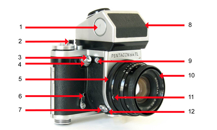
1 Metering prism battery cover
2 Film advance lever
3 Shutter release
4 Shutter release lock
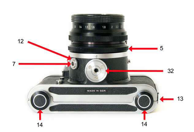
5 Lens retaining ring
6 Delayed action (self-timer)
tensioning lever
7 Flash connection socket
8 Metering prism
9 Strap lug
10 Lens
11 Lens aperture stop-down lever
12 Flash cable locking ring |
|
|
|
|
|
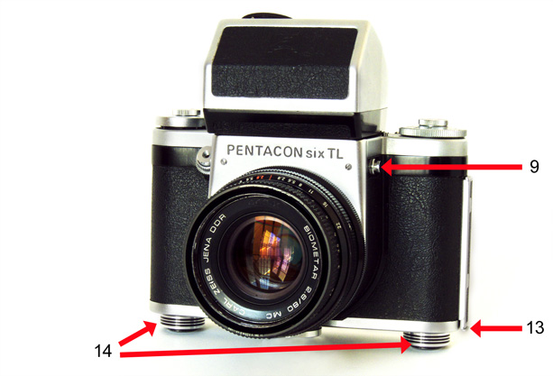
9 Strap lug
13 Back opening catch
14 Spool retaining knob |
[pts2.jpg]
|
|
|
|
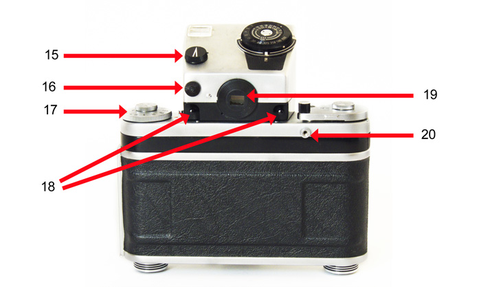
15 Metering prism on/off switch
16 Viewfinder shutter knob
17 Shutter speed setting dial
18 Metering prism release buttons |
[pts3.jpg]
|
19 Viewfinder
20 Mirror pre-release socket |
|
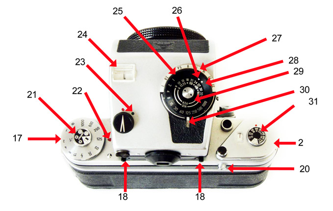
17 Shutter speed setting dial
18 Metering prism release buttons
21 Film type reminder dial
22 Shutter speed index mark
23 Metering prism switch on position
24 External metering needle window |
[pts4.jpg]
|
2 Film advance lever
20 Mirror pre-release socket
25 Middle meter adjustment dial (with
shutter speeds)
26 Film sensitivity setting index (for
camera with standard
focussing screen)
27 Outer meter adjustment dial (with lens
apertures)
28 Film sensitivity setting index (for
camera with fresnel
or Rollei focussing screen)
29 Inner meter adjustment dial (with film
sensitivity
settings)
30 Meter mode index point
31 Film speed reminder dial |
|
7 Flash connection socket
12 Flash cable locking ring
14 Spool retaining knob |
[pts5.jpg]
|
5 Lens retaining ring
32 Tripod socket
13 Back opening catch |
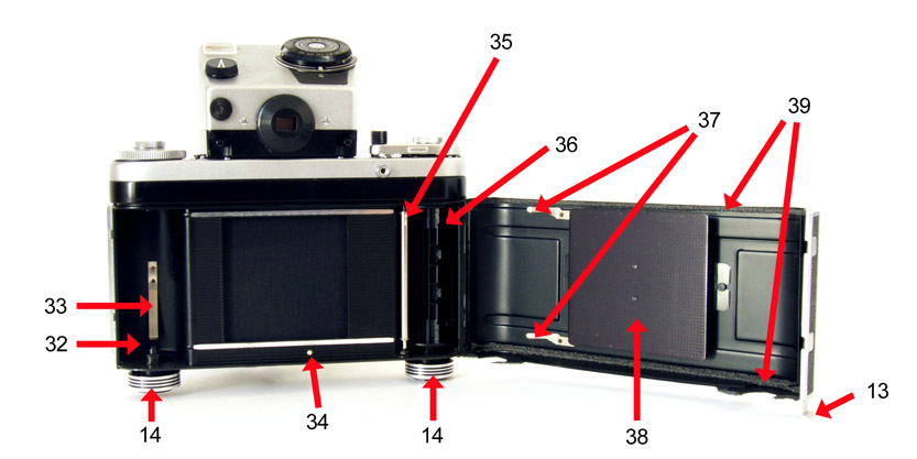
14 Spool retaining knob
32 Film feed chamber
33 Film retaining spring |
[pts6.jpg]
|
34 Film loading index point
35 Film advance control spindle
36 Film take-up chamber & spool
37 Springs to press the film against the
film advance
control spindle
38 Film pressure plate
39 Foam light-proofing material
13 Back opening catch
|
17 Shutter speed setting dial
29 Inner meter adjustment dial (with
film sensitivity
settings)
41 Lens aperture control ring
42 Lens focussing ring
43 Index point for aperture and focus
settings with normal
film |
[pts7.jpg]
|
44 Index point for aperture and focus
settings for use
with Infra-Red film
45 Depth-of-field scale
46 Aperture values
27 Outer meter adjustment dial (with lens
apertures)
25 Middle meter adjustment dial (with
shutter speeds)
40 Frame counter
30 Meter mode index point
47 Film advance de-blocking lever (beneath
film advance
lever) |
| The release
button on the top plate for the viewfinder locking pin
can be seen here (about
half way down the page). This pin prevents accessories that are merely slid into
place (the waist level finder and the magnifier head)
from accidentally sliding off. (The prisms have
their own locking mechanism.) There are further
pictures of this pin and its release button here. |

[C387_14Anum.jpg]
|
47 Film advance de-blocking lever
(beneath film advance
lever) |
|
 [C387_16Anum.jpg]
|
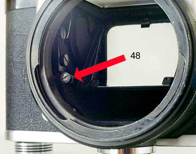
48 Lens aperture stop-down lever |
For detailed instructions on how to load the
camera, click
here.
To return to the instructions front page, click here.
To return to “The Cameras” page, click here.
Home
© TRA November 2008 Revised: January 2019